 Sunvim Motor
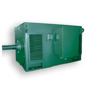
Deconstructing Motor Overload Faults & Modern Industrial Protective Architectures
In heavy industrial processing, manufacturing, and municipal applications, the three-phase electric induction motor functions as the primary mechanical driver. Yet, these critical components operate within harsh environments characterized by voltage fluctuations, mechanical load spikes, and ambient temperature extremes. An overload fault represents one of the most persistent and damaging risks to motor operational lifespans, manifesting as a prolonged operating current that exceeds the motor’s rated current limit. Left unmitigated, these events induce high temperatures within the stator windings, accelerating winding insulation degradation (specifically cracking the dielectric film) and eventually culminating in catastrophic short-circuits, fire risks, and expensive unscheduled facility downtime.
A certified, robust electric motor must incorporate intelligent mechanical safety standards to mitigate thermal and electrical fatigue. Selecting a CE Certification Overload Fault Supplier ensures that the motor machinery satisfies the strict health, safety, and environmental protection benchmarks of the European Economic Area (EEA). This white paper provides industrial engineers, procurement officers, and system integrators with an expert-level technical evaluation of motor overload fault kinetics, standard protective mitigations, macroscopic market paradigms, and the dynamic engineering framework employed by global leaders such as Shandong Sunvim Motor Co., Ltd.
Electro-Thermal Runaway Kinetics
During overload events, the motor stator winding current ($I$) increases dramatically. The rate of heat generation within the copper windings escalates proportionally to the square of the current ($I^2R$ losses), causing an exponential jump in temperature that degrades the motor insulation class over time.
Dynamic Trip Curve Profiles
Advanced overload relays track a thermal replica model of the motor. Class 10, Class 20, and Class 30 trip settings are designed to trip the system offline at 600% of the maximum current rating within 10, 20, or 30 seconds respectively, optimizing both protection and uptime.
CE Compliance & IEC Standards
CE marking confirms adherence to the Low Voltage Directive (2014/35/EU) and EMC Directive (2014/30/EU). Incorporating IEC 60947-4-1 standards ensures that mechanical starters and contactors maintain physical trip safety levels even during severe overcurrent scenarios.
Macro-Industry Challenges: Why Single-Sourced Standards Cause Mechanical Systems Failure
Historically, electric motors operated with high service factors, allowing them to run up to 15% above their nameplate rating without catastrophic failure. Modern optimized energy designs, such as high-efficiency IE4 and IE5 permanent magnet synchronous motors, feature extremely precise mechanical and electromagnetic tolerances. Consequently, they are more sensitive to thermal overshoots caused by overload faults. Unregistered global motor supply lines frequently use subpar winding wire insulation, lack PTC thermistor protection, and exhibit rotor manufacturing eccentricities that lead to unbalanced magnetic pull. When these lower-tier motors experience minor mechanical loads or input voltage imbalances, they quickly slip into a severe overload condition, tripping distribution lines and burning out components prematurely.
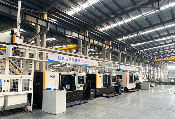
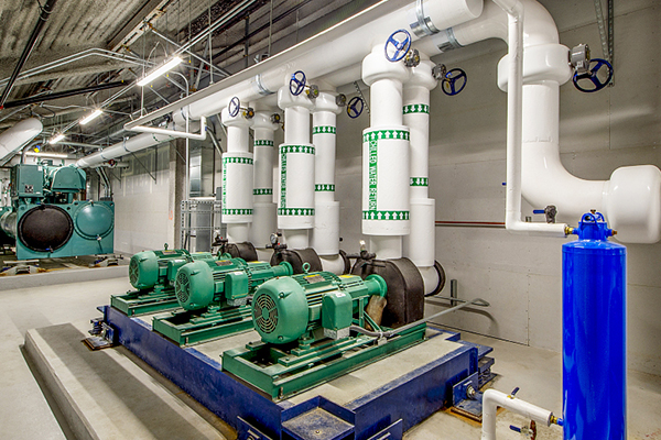
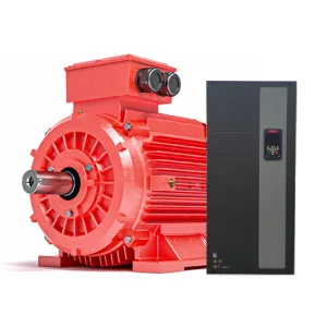
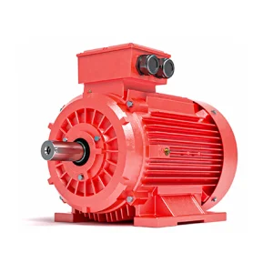
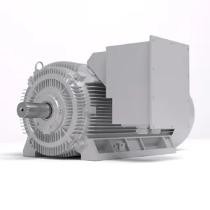
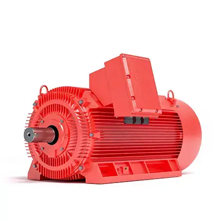
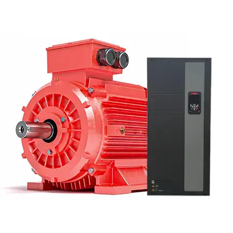
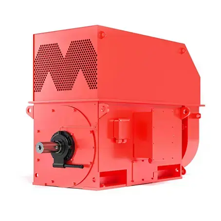
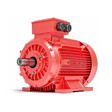
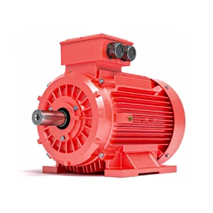
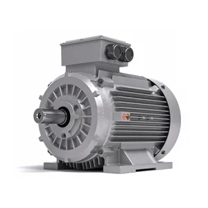
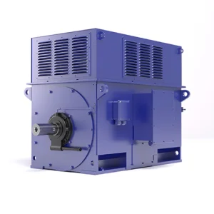
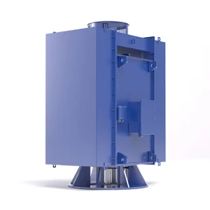
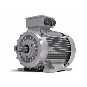
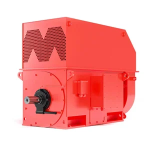
A reliable plant system relies on a multi-tiered defense. The motor must be designed to withstand reasonable transients, and its internal winding topology must incorporate embedded sensors (PT100/PTC) that actively communicate with external Variable Frequency Drives (VFDs) or soft starters. Global enterprises require suppliers with the manufacturing capability to construct specialized, heavy-duty frame configurations—such as rib-cooled cast iron structures and modular high-voltage housings—capable of maintaining thermal stability even during intermittent overload stresses.
| Overload Protection Technology | Operational Mechanism | Primary Disadvantage | Best Applied Scenarios |
|---|---|---|---|
| Bimetallic Thermal Relays | Differential expansion of two bonded metals under heat breaks the control circuit contacts. | No protection against rapid rotor locking; sensitive to ambient temperatures. | Constant load centrifugal fans and standard water pumps. |
| Solid-State Electronic Relays | Microcontrollers measure current waveforms via integrated CTs and calculate the I²t thermal profile. | Requires external power, higher starting investment. | Heavy-inertia industrial mixers, variable duty cycles. |
| PTC Thermistors (Embedded) | Internal semiconductor sensors experience a sharp resistance spike at defined transition temperatures. | Cannot detect localized overcurrent before heat reaches the sensor. | Submersible pumps, high-voltage modular industrial compressors. |
| Digital Twin IoT Vibration/Current Analysis | Stator Current Signature Analysis (MCSA) and cloud edge telemetry map early fault anomalies. | Complex software setup and network integration. | Critical deep-shaft mining machinery and high-value metallurgy plants. |